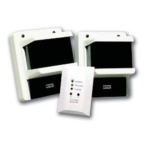
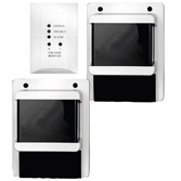
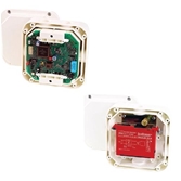
The D297 12 V Projected Beam Smoke Detector is used in clear open structures such as arenas, atriums, auditoriums, ballrooms, churches, factories, museums, and warehouses. Each D297 detector consists of a transmitter, a receiver, and a remote indicator plate. Because the transmitter and receiver typically mount on the ceiling or high on walls or columns, they provide an effective and unobtrusive means of supervising public areas for fire protection.
FUNCTIONS
Aim Mode
When the cover is removed from the receiver, the receiver goes into aim mode. When the cover is
removed from the transmitter, the transmitter stops transmitting. Pressing the Aim Mode button on the transmitter allows transmission while the cover is off. For fine tuning which requires a measurable voltage at the receiver, the covers must be off and transmission is necessary.
Alarm Operation
The transmitter emits a pulsed infrared beam. The receiver measures the intensity of the beam over a period of time and compares this data with an alarm threshold. Select one of six levels of sensitivity for the alarm threshold through a switch on the receiver. If the receiver senses signal strength below the preset alarm threshold in excess of the alarm period it signals an alarm.
Signal Loss Compensation
The receiver automatically compensates for the gradual loss of signal due to dust and dirt build-up on the cover. The receiver measures the intensity of the pulsed infrared beam emitted by the transmitter over a period of time and compares this data with a preset trouble threshold. When 50% of the signal is lost or the signal gains 20%, the receiver sends a trouble signal to the control panel. When the dust and dirt build-up is cleaned or the blockage is removed, the detector automatically resets.
Tamper Detection
If the covers to the transmitter or receiver are removed, the detector sends a trouble signal to the control panel.
Trouble Detection
The receiver measures the intensity of the pulsed infrared beam emitted by the transmitter over a period of time and compares this data with a preset trouble threshold. When 90% or more of the signal is lost for more than 20 seconds, as might happen if an object blocked the beam, the receiver sends a trouble signal to the control panel.
Mounting Considerations
The transmitter and receiver mount on standard 3.5‑inch or 4‑inch square or octagonal back boxes or European Beza boxes. Mount the detectors directly to the ceiling or to side walls. Do not mount the units so that the beam runs closer than 4 in. (10.2 cm) to the intersection of the wall and the ceiling. Otherwise, place and space the detectors according to NFPA 72.
Notice
The beam path should be clear of moving objects. Avoid areas subject to normal smoke concentrations such as kitchens and garages. Do not install units where normal ambient temperatures are below -22°F (-30°C) or above +130°F (+54°C).
Lateral Spacing Between Systems
For adequate coverage, the lateral spacing between adjacent detector systems must not exceed 60 ft (18 m).
Wiring
System wire terminals accept 18 AWG to 12 AWG (ISO 0.75 mm2 to 4 mm2) solid wires.
Environmental Considerations
Relative Humidity: 0% to 95%, non-condensing
Temperature (ambient): -22°F to +130°F (-30°C to +54°C)
For UL Listed installations, +32°F to+100°F (0°C to +38°C)
Mechanical Properties
Dimensions (H x W x D): 7 in. x 5.5 in. x 5.5 in. (17.8 cm x 14 cm x 14 cm)
Transmission Range: 30 ft (9 m) to 350 ft (107 m)
Power Requirements
Current (alarm): Receiver: 75 mA, Transmitter: 20 mA
Current (standby): Receiver: 50 mA, Transmitter: 20 mA
Voltage (operating): 10.2 VDC to 15 VDC

 Viber / Zalo: